
2026-10-28 13:41:17
A container home roof needs three things to work together: a reliable route for rainwater, continuous weather protection at joints and openings, and structural design for the actual project conditions. Roof shape alone does not establish any of them. A flat-looking roof can have designed drainage falls, while an added pitched roof introduces its own supports, connections and wind exposure.
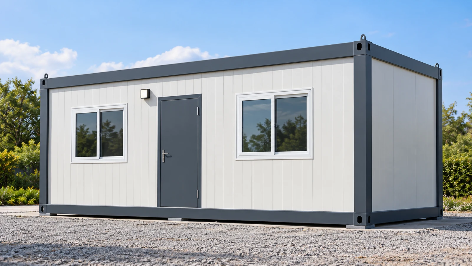
Converted shipping-container homes and purpose-built modular houses do not necessarily share the same roof construction. Lumin Mod’s integrated-house specifications, for example, describe a flat roof with organized internal drainage. That is a starting point for reviewing the selected system—not evidence that every container home uses the same drainage arrangement, or that a standard configuration suits every location.
What Roof Designs Are Used on Container Homes?
Low-Slope and Flat-Looking Roofs
A level roof edge can conceal a sloping drainage surface. Water must still reach an outlet without being trapped by seams, raised details or local depressions. The required slope depends on the chosen roof covering and assembly; it cannot be selected from the building’s “container home” label.
Metal roofing is not one interchangeable product. Different panel profiles, seams and joint systems have different installation requirements. A roof covering intended to shed water down a slope should not be assumed suitable for prolonged standing water. Review the actual roof-system details and installation requirements, not simply a photograph of a metal sheet.
For Lumin Mod’s container integrated house roof system, the relevant product information identifies internal drainage. The next useful document is the selected model’s drainage drawing, showing the collection points and discharge route. An external elevation alone cannot confirm those details.
Pitched Roofs and Secondary Roof Structures
A pitched roof or secondary over-roof can provide a different rainwater-shedding arrangement. However, its weight, wind loads, supports, flashings and discharge points must be coordinated with the building below. It should not be treated as a lightweight accessory that can be attached wherever convenient.
| Roof approach | Useful design question | Important limitation |
|---|---|---|
| Low-slope or flat-looking roof | How do the finished falls lead to the outlets, and how can the drainage system be inspected? | A clean box-shaped exterior does not reveal the roof’s slope, drain capacity or blockage response. |
| Pitched roof or secondary over-roof | Where do the added supports transfer loads, and where does the shed rainwater go? | The added roof needs a coordinated structural and weatherproofing design; it does not automatically correct defects below. |
Choose a roof for the location, building configuration and maintenance arrangements. There is no single roof shape that removes the need for drainage and connection design.
How Does Roof Drainage Work on a Container Home?
Roof Slope and Water Flow Paths
Trace the full route: rain falls on the roof, moves across the drainage surface, enters an outlet, travels through the drainage system and discharges away from vulnerable building areas. A working roof outlet is only one part of that route. A blocked downstream pipe or poorly located discharge can still create problems.
The finished geometry matters as much as the intended geometry. Structural deflection, incorrect installation or uneven support can change low points and leave water behind. Persistent ponding therefore calls for investigation of the roof and its supports—not simply another layer of coating. Do not alter foundation levels to create roof drainage without the building designer’s approval.
Drainage capacity depends on the contributing roof area, the rainfall conditions used for design and the outlet system’s performance. Counting outlets does not establish capacity. When modules are joined, confirm whether their roofs still drain independently or whether the connection changes the area feeding an outlet.
Gutters, Scuppers and Internal Drains
| Drainage component | How it works | What to examine |
|---|---|---|
| Gutter | Collects runoff along a roof edge or another designed collection line and leads it toward an outlet. | Falls, joints, supports, downpipe connections and access for clearing debris. |
| Scupper | Lets water pass through an opening in a raised roof edge or wall. | Inlet height, opening size, waterproof lining and where the discharge lands. |
| Internal drain | Collects water at a roof inlet and carries it through a connected pipe route. | The roof-to-drain seal, pipe continuity, maintenance access and final discharge. |
These are general system descriptions, not a list of features present on every Lumin Mod unit. For the selected model, establish which components are actually supplied and which connections must be completed on site.
Primary Drainage and Emergency Overflow
The primary system handles normal drainage. Where raised edges or other features can retain water, the designer also needs to address what happens if the primary outlet becomes blocked. Water accumulation adds load; a roof that appears watertight can still develop a structural drainage problem.
Where required by the applicable design criteria, secondary drainage provides an overflow route before water exceeds the roof’s design limits. Its level, capacity and discharge arrangement need to be coordinated with the structure. An extra inlet that depends on the same blocked section of pipe may not provide independent protection.
The question is not simply “Does the roof have a drain?” It is “How much water can this roof collect, where can it leave, and what happens when the normal path fails?”
Which Roof Details Are Most Vulnerable to Water Leakage?
Roof Edges and Roof-to-Wall Connections
Rain protection has to remain continuous where a roof meets an edge, wall or upstand. Flashing directs water across those transitions and back toward the exterior drainage surface. An exposed joint that relies only on a smear of sealant provides a different level of protection from a properly detailed, mechanically supported transition.
Review the sequence of overlapping materials and the direction water will travel. Also consider movement: metal components expand and contract with temperature changes. The joint needs a compatible arrangement for that movement rather than a rigid connection that can pull the weather seal apart.
Penetrations, Fasteners and Equipment Supports
A vent, cable route, equipment bracket or other penetration interrupts the roof’s water-control layer. It needs a detail compatible with the actual roof covering, not a generic patch selected after the opening is cut. The flashing must connect to the surrounding drainage surface so water is directed away from the opening.
Equipment supports introduce a second question: where does the load go? A watertight-looking support is not necessarily structurally adequate, and a strong fixing is not necessarily watertight. Roof attachments need both checks. Keep access available for inspection and future replacement of seals or components.
Waterproofing at Modular Roof Connections
Two individually completed modules do not automatically form one weatherproof building when placed side by side. Their connection can create a new seam, an interrupted drainage path or a low channel between roof edges. The connection drawing should show how the roof finishes, joint cover and drainage arrangement work together.
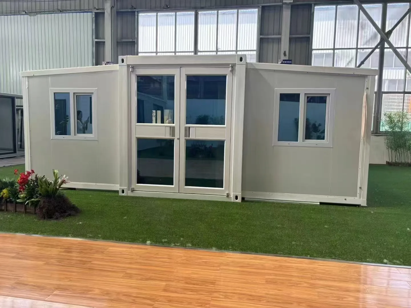
This matters particularly with site-assembled systems such as Lumin Mod’s quick assembly container houses. Factory-prepared components still require the specified site connections. Confirm who supplies the connection materials, who installs them and how the completed junction will be inspected.
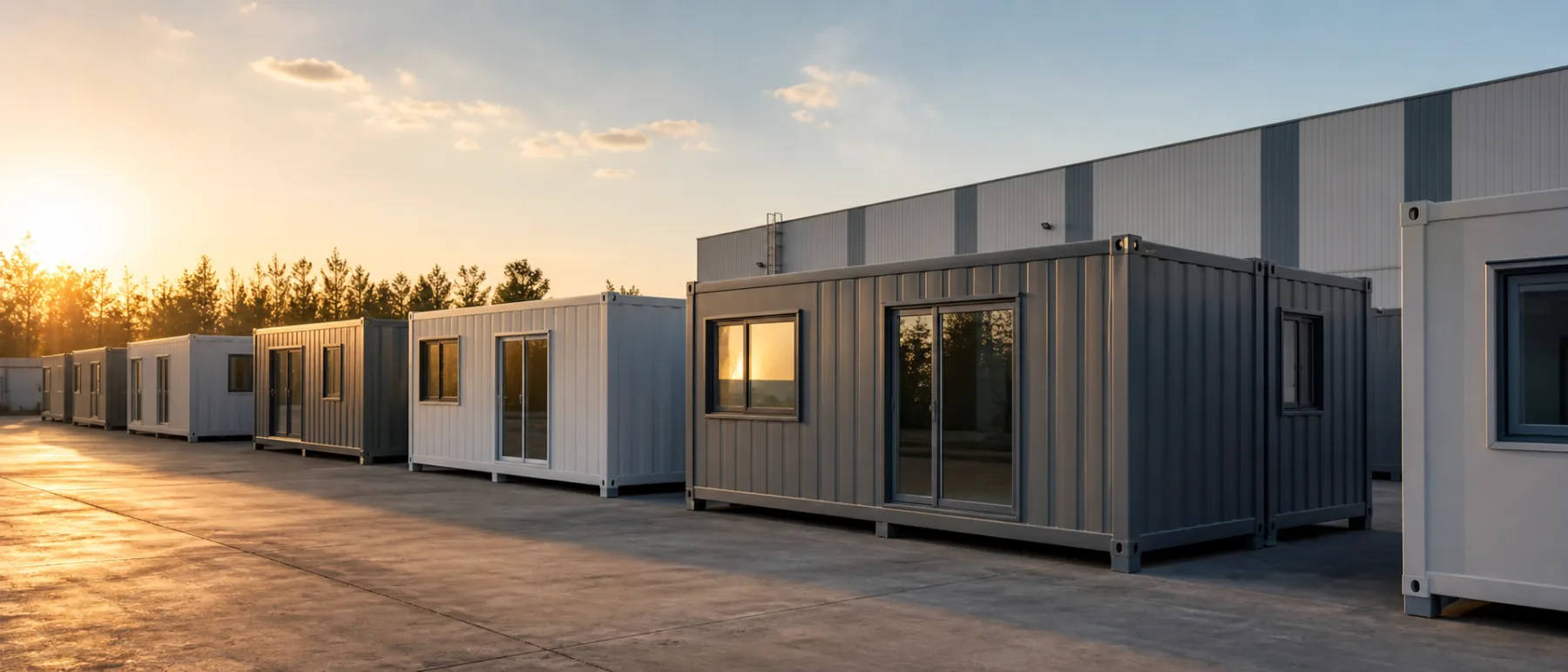
Assess the actual module layout rather than repeating a single-unit detail everywhere. An end-to-end connection, a side-by-side connection and a junction below a taller module can present different water paths and access constraints. Those differences belong in the project details before production and installation.
How Do Insulation, Weather and Structural Loads Affect Roof Design?
Insulation and Moisture Control
Rainwater leakage and condensation are different mechanisms. Rain enters from outside through a defect or inadequate detail. Condensation forms when moisture conditions and surface temperatures allow water vapor to become liquid. A wet ceiling therefore does not, by itself, identify a roof-covering failure.
The roof’s insulation continuity, air leakage paths and vapor-control strategy must be considered together. Steel framing can form thermal bridges, and gaps in the air-control layer can carry moist air into colder parts of the assembly. Adding insulation without checking those pathways may leave the moisture mechanism unresolved.
Lumin Mod’s integrated-house specification lists a color-coated steel sheet, glass-wool insulation and a foil layer in the roof build-up. A layer list alone does not establish vapor-control performance: continuity, joints and the climate-specific assembly design still need confirmation. Do not prescribe the same vapor-retarder location for every climate.
Rain, Snow, Wind and Ponding Loads
Drainage and structural design are connected. Accumulated water adds weight; deflection can deepen a low point and allow more water to collect. Snow introduces different loading conditions, while wind can act on the roof covering, its fasteners and any added roof structure. These actions require project-specific assessment rather than a general statement that the steel frame is strong.
A roof live-load figure is not a universal roof-capacity rating. The Lumin Mod integrated-house page lists a roof live load of 0.5 kN/m² for its described configuration. That number is not, by itself, an allowable snow load, a permitted depth of ponding water or approval for a rooftop terrace. It does not replace the required project load checks and combinations.
Solar equipment, tanks, storage, decking and secondary roofs should not be added on the assumption that the original roof can carry them. Their supports and connections must transfer the relevant loads into a verified structure. A roof that can be inspected under an approved access arrangement is not necessarily designed for routine occupancy.
What Should Buyers Verify Before Ordering a Container Home Roof?
A useful technical review connects each promised feature to a drawing, scope item or project requirement. “Waterproof roof” is too broad to define the roof covering, its interfaces or the conditions under which it will be installed.
| Document or information | What it should resolve | Why it matters |
|---|---|---|
| Selected roof assembly | Covering, supporting layers, insulation, joints and relevant material specifications. | Identifies the actual system rather than a generic product description. |
| Drainage layout | Falls, collection points, outlet connections, discharge route and the blockage response required for the project. | Shows a complete water path instead of isolated drainage components. |
| Waterproofing details | Edges, roof-to-wall junctions, penetrations and connections between modules. | Addresses the points where the water-control layer changes direction or is interrupted. |
| Structural design basis | Site conditions, building layout, supports, relevant loads and any proposed additions. | Separates published product data from the checks needed for the specific building. |
| Factory and site responsibilities | What is completed before shipment, what remains on site and who supplies each connection component. | Prevents unassigned junctions or unfinished interfaces at handover. |
| Inspection and maintenance plan | Safe access, inspectable components, required checks and repair guidance. | Makes the installed roof maintainable throughout its use. |
These are items to request for the project; they are not a claim that every supplier has already published all the documents. Any inspection or test record should identify the unit or configuration, the method and the acceptance basis. A demonstration video alone does not establish performance for a different layout or installation.
Agree on how site joints and drainage connections will be checked before they become concealed. Any water-testing procedure must be appropriate to the roof and approved for the project; deliberately blocking outlets or flooding a roof without a suitable procedure can create unnecessary loads and damage.
How Can Roof Drainage and Waterproofing Be Maintained?
Maintenance should preserve the intended water path and identify changes in vulnerable details. Use the roof-system instructions and local exposure conditions to set inspection arrangements; a single universal interval is not appropriate for every roof or site. Inspection access must also suit the roof’s load and safety provisions.
Check accessible collection points for debris, and have obstructed outlets or pipework cleared using appropriate procedures. Examine flashing, joints and penetrations for displacement, damaged seals or deterioration. New ponding, corrosion staining or repeated interior dampness should trigger an investigation rather than repeated surface patching.
Record when and where interior moisture appears. Wetting associated with rain can direct attention toward external water entry, while condensation needs investigation of temperature, humidity and air leakage. These are clues, not a diagnosis: water can travel within an assembly before becoming visible.
Finally, treat every new roof opening or attachment as a design change. Review the support, weatherproofing and drainage consequences before the work begins. Preventive inspection cannot compensate for an unsuitable roof detail or an unverified structural addition.
For a proposed Lumin Mod installation, discuss the project’s roof requirements using the destination, module arrangement, intended use and any planned rooftop equipment. The aim is to confirm a roof assembly, drainage route and set of connection details that work together for that specific building.